
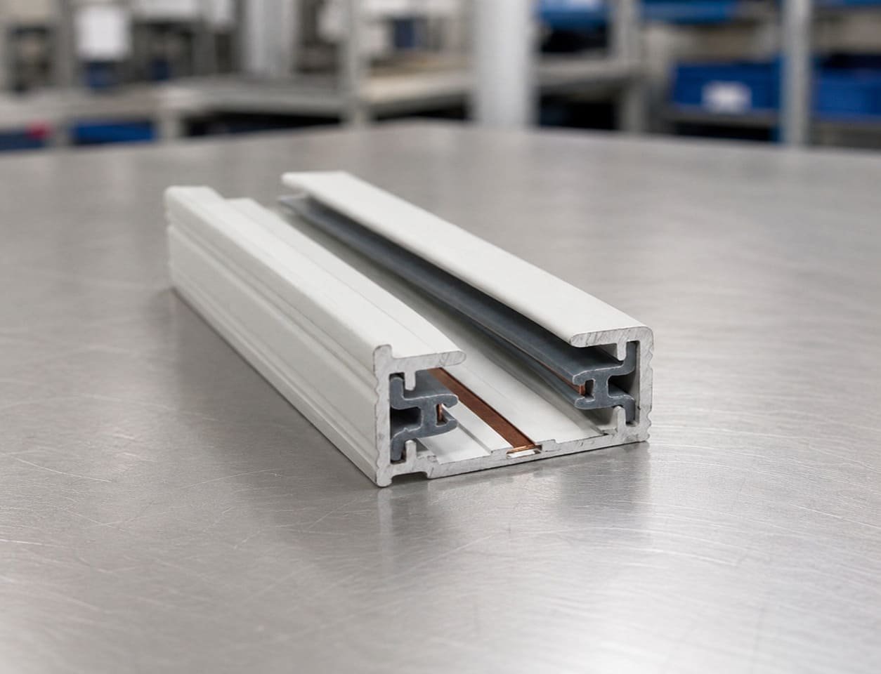
Conductive Profile for Lighting System
- Challenges Resolved
- 5
- Processes Applied
- 2
- Production Steps
- 6
01 · Project Background
Understanding the Client's Requirements
A lighting-system customer required a linear profile combining conductive copper elements with an insulating plastic structure. The conventional design involved separate conductive and plastic components that required additional positioning and assembly. The project objective was to integrate the conductive elements directly into the plastic profile during continuous extrusion while maintaining the required conductor position and overall profile geometry.
02 · Manufacturing Challenges
What Made This Project Technically Demanding
-
Maintaining accurate copper conductor position within the plastic profile
-
Controlling profile geometry around embedded conductive elements
-
Achieving stable integration between metal and plastic during continuous extrusion
-
Maintaining electrical separation between conductive sections
-
Ensuring repeatable conductor positioning during batch production
03 · OKAWA Solution
How We Engineered the Answer
OKAWA evaluated the conductor geometry, plastic profile structure and required conductor positions as an integrated extrusion system rather than treating the metal and plastic parts as separate components. Dedicated tooling and conductor-guiding structures were developed to continuously feed and position the copper elements while the plastic profile was formed around them. During sampling, conductor position, profile dimensions and the metal-plastic interface were checked and the process parameters were adjusted for stable continuous production. This integrated manufacturing approach allows conductive and insulating functions to be incorporated into one continuous profile and can reduce subsequent positioning and assembly operations compared with separately manufactured components.
04 · Production Flow
Step-by-Step Manufacturing Process
-
Step 01
Structure Review
Evaluate the profile geometry, conductor arrangement, insulation structure and application requirements.
-
Step 02
Tooling & Conductor Guidance
Develop extrusion tooling and guiding structures for controlled copper positioning.
-
Step 03
Co-extrusion Sampling
Feed copper elements and plastic material through the integrated co-extrusion process to produce initial samples.
-
Step 04
Position & Dimension Verification
Check conductor position, profile geometry and critical dimensions.
-
Step 05
Process Optimization
Adjust tooling and processing conditions to improve repeatability and continuous production stability.
-
Step 06
Cutting & Final Inspection
Cut profiles to the required length and inspect finished components before delivery.
05 · Delivery Results
Final Outcomes & Project Value
The project resulted in an integrated copper-plastic profile combining conductive elements and an insulating structural body in a single continuously manufactured component. After sample validation, the manufacturing process was prepared for repeatable batch production, reducing the need to separately position conductive elements during downstream assembly.